The question a contractor asks before pricing a ceiling-ducted all-in-one unit: will the far bedroom get enough air, or will the unit run out of static before the last diffuser? The answer comes from three numbers: the airflow the suite needs, the fan curve of the unit, and the resistance of the longest duct run. Here is how to work it through, with the EXINDA Aura HPERV as the example.
1. Decide the airflow the suite needs
The HPERV is rated at 430 CFM in heating and 400 CFM in cooling at 0.30 in. w.g. Split that across the rooms in proportion to their heating and cooling loads, with the living area usually taking the largest share. The room with the longest duct run is the one that sets the design; if it gets its share at the design static, the others will.
2. Read the fan curve, not the nameplate
A ducted unit delivers less air as duct resistance rises. The HPERV publishes the whole curve, so you can read airflow at the static your ducts actually produce:
| External static (in. w.g.) | 0 | 0.1 | 0.2 | 0.3 | 0.4 | 0.5 |
|---|---|---|---|---|---|---|
| Heating, high speed (CFM) | 638 | 570 | 500 | 430 | 339 | 320 |
| Cooling, high speed (CFM) | 600 | 530 | 460 | 400 | 300 | 280 |
If a manufacturer only gives you a maximum static with no airflow beside it, ask for the curve. A maximum static figure on its own tells you nothing about how much air reaches the last room.
3. Estimate the resistance of the longest run
Use the pressure-drop assumptions from the submittal; they are conservative enough for a first pass:
| Component | Pressure drop |
|---|---|
| Straight duct | 2 Pa per metre (about 0.6 Pa per foot) |
| 90° elbow | 6 Pa |
| Balancing damper | 8 Pa |
| Supply diffuser | 30 Pa |
| Return grille and filter | Included in the unit's rated static |
Worked example, one-bedroom suite, unit near the exterior wall, far bedroom diffuser 33 ft (10 m) away with three elbows:
- Straight duct 10 m × 2 Pa = 20 Pa
- 3 elbows × 6 Pa = 18 Pa
- Balancing damper = 8 Pa
- Diffuser = 30 Pa
- Total ≈ 76 Pa ≈ 0.30 in. w.g.
That lands on the rated point: 430 CFM heating, 400 CFM cooling. This is what the submittal means when it says the rated point corresponds to about 39 ft of equivalent duct.
Stretch the same run to 50 ft (15 m) with four elbows: 30 + 24 + 8 + 30 = 92 Pa ≈ 0.37 in. w.g. Reading the curve, heating airflow drops to roughly 365 CFM. Whether that is acceptable depends on the load split; if not, shorten the run, go up a duct size to cut the straight-duct loss, or move the unit closer to the middle of the suite.
Notice which item is largest: the diffuser at 30 Pa. Choosing a low-resistance diffuser buys more than shaving a few feet of duct.
4. Pick the supply connection
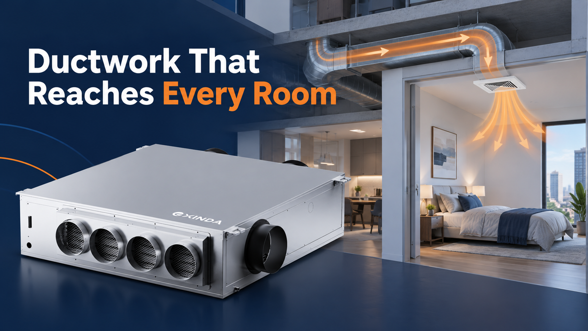
The HPERV offers two supply arrangements: one 28 × 8 in rectangular opening for a single trunk, or four Ø6 in round spigots for direct branches. Four rounds are usually the simpler choice in a suite with three or four rooms; the trunk is better when the ceiling is tight and one duct has to snake around obstructions. Return is a Ø8 in round from a grille in a hallway or the living area; keep it away from the nearest supply diffuser so conditioned air is not pulled straight back to the unit.
5. Do the outdoor ducts as a separate calculation
The outdoor side has its own fan and its own static budget: 650 CFM at 0.36 in. w.g. through a 12 × 8 in intake and a 10 × 8 in exhaust, both rectangular. Add 12 Pa for each weather louver. Keep the two openings at least 4.1 ft apart, insulate both ducts with 20 mm (0.8 in) closed-cell insulation with a vapour barrier, and fit a 4 in flexible connector at each unit connection for vibration isolation. Bathroom exhaust connects to the Ø6 in spigot.
6. Leave room to service it
A unit that fits above the ceiling but cannot be serviced is a callback waiting to happen. The HPERV needs a main access corridor of at least 59-11/16 in, a service opening depth of 22-5/8 in, a 16 × 10 in opening at the air inlet, 16 in clear at the electrical compartment, a 6 × 9-11/16 in filter access, and 2 in side clearance. Coordinate the ceiling access panel with the filter and electrical panel positions before the ceiling goes up, not after.
7. Condensate
DN15 drain, 3° fall, a P-trap with at least 3-3/4 in horizontal width and 1/2 in vertical drop, and insulation on the whole run. If the extension pipe is longer than 40 in, add a tee vent so the trap does not siphon.
Pre-order checklist
- Longest supply run calculated and under 0.30 in. w.g., or the airflow at the actual static confirmed as acceptable.
- Supply connection chosen (28 × 8 trunk or 4 × Ø6).
- Return grille location at least a few feet from any supply diffuser.
- Two exterior openings located, 4.1 ft apart, louvers selected.
- Ceiling depth 11-1/8 in plus hanging rods; service opening positioned over the filter and electrical panel.
- Drain route with a continuous 3° fall.
- Circuit sized to MCA 20 A / MOP 30 A, hardwired 208–240 V.
Dimension drawings, the duct connection layout and the clearance table are in the submittal on the HPERV product page. For choosing between a ducted and a wall-mounted unit in the first place, see Ceiling-ducted vs wall-mounted all-in-one heat pumps. On a new building, the openings, drain and duct runs above are the items the basis of design fixes before the curtain-wall shop drawings; see PTHP with integrated ERV for new multifamily construction.
Have a unit plan? Send it with the proposed unit position to info@exindagroup.com and ask for project selection support. You get back a duct layout suggestion with the static check done.