The all in one heat pump AURA HPERV gives apartment designers a way to place heating, cooling and energy recovery ventilation inside the building without a separate outdoor condensing unit—and without automatically locating the equipment next to an exterior wall.
That matters when the most practical installation space is above a laundry room, several metres from the façade. It also matters when neighbouring apartments have mirrored floor plans and need opposite-handed equipment arrangements.
For engineers, installers and distributors evaluating an alternative all-in-one HVAC system, EXINDA offers two useful selection features: mirror configurations and documented outdoor-side airflow of 650 CFM at 90 Pa external static pressure. Together, they help project teams coordinate the equipment with the apartment layout.
Can the unit be installed 7–10 metres from the exterior wall?
A duct route in this range is a workable design possibility for AURA HPERV. Using the typical pressure-loss assumptions in the EXINDA submittal, a layout with a 7-metre intake duct and a 7-metre discharge duct calculates to 76 Pa. Extending both ducts to 10 metres gives 88 Pa, close to the documented 90 Pa operating point.
Here is what those examples include:
| Outdoor air path | 7 m intake + 7 m discharge | 10 m intake + 10 m discharge |
|---|---|---|
| Straight duct at 2 Pa/m | 28 Pa | 40 Pa |
| Four 90° elbows in total, at 6 Pa each | 24 Pa | 24 Pa |
| One intake and one discharge terminal, at 12 Pa each | 24 Pa | 24 Pa |
| Calculated external pressure loss | 76 Pa | 88 Pa |
| Remaining allowance against 90 Pa | 14 Pa | 2 Pa |
These are calculated routing examples using the submittal’s typical component losses, with both outdoor ducts included in one pressure budget. The lengths are actual duct runs, rather than straight-line measurements across the apartment. Duct sizing and selected fittings must deliver the stated losses at the design airflow. Additional components, such as dampers, must be included where fitted.
The 7-metre example offers more room for additional resistance; the 10-metre example benefits from a simpler route. For example, removing two unnecessary elbows reduces the 10-metre calculation from 88 Pa to 76 Pa, restoring 14 Pa of allowance.
This gives the designer a practical starting point: keep the preferred laundry location, then work on the duct route, fittings and exterior terminals to preserve airflow.
Why outdoor intake pressure matters as much as room supply pressure
When selecting a ducted system, it is natural to check whether the indoor fan can deliver conditioned air to bedrooms and living spaces. An all-in-one heat pump also needs enough airflow through its outdoor heat-exchange circuit.
Outdoor air must travel from the façade opening to the unit and return outside through the discharge duct. If the unit is above a laundry room deeper inside the apartment, both paths can become substantial.
For the documented AURA model, EXINDA specifies:
| Air system | Airflow at stated external static pressure |
|---|---|
| Outdoor heat-exchange circuit, cooling and heating | 650 CFM at 90 Pa — approximately 307 L/s at 0.36 in. w.g. |
| Indoor conditioned-air supply, cooling | 400 CFM at 75 Pa — approximately 189 L/s |
| Indoor conditioned-air supply, heating | 430 CFM at 75 Pa — approximately 203 L/s |
The outdoor 650 CFM figure describes airflow serving the heat pump’s outdoor heat exchanger. The ERV’s fresh-air ventilation duty is a separate selection requirement.
For buyers comparing systems, the useful question is therefore: “What airflow can this unit deliver through my complete outdoor intake and discharge route?” A free-air fan rating or an indoor supply-pressure figure alone does not answer it.
AURA’s documented outdoor operating point provides a numerical basis for that comparison. Review the EXINDA AURA HPERV product page and download the technical submittal for the airflow tables, installation details and typical pressure-loss assumptions.
All in one heat pump AURA HPERV mirror configurations
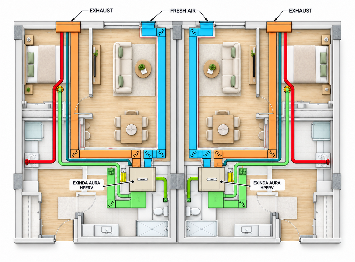
In a pair of mirrored apartments, the laundry rooms, bathrooms and service zones may sit on opposite sides of the dividing wall. Using the same equipment orientation in both apartments can introduce avoidable duct crossings, extra bends or longer connections.
EXINDA can provide AURA HPERV in mirror configurations, allowing the equipment arrangement to match the handedness of the apartment.
The benefit is practical. A matching configuration can keep connections closer to their intended duct routes and reduce the need to redesign the installation for the opposite apartment. Across repeated apartment types, that can simplify drawing coordination and installation planning.
It also makes better use of the available static pressure. In the calculation above, every avoided elbow saves 6 Pa under the stated assumptions. Where a mirror arrangement removes two elbows, the saving is 12 Pa—pressure that can instead support a longer route or provide additional design allowance.
The cover illustration shows this principle: two mirrored apartments with AURA units positioned near the laundry areas and coordinated duct routes to the exterior. It is a layout concept, rather than a dimensioned installation drawing.
Where should AURA HPERV be installed?
An accessible ceiling position above a laundry or utility room is a good location to consider first. It can keep the equipment away from the apartment’s main living area while placing drainage and maintenance access in a service zone.
A suitable bathroom ceiling service space can also be considered where equipment access, moisture protection and electrical placement requirements can be met. Provide a dry, accessible equipment zone away from direct shower or bath exposure.
This arrangement supports acoustic planning by separating the equipment from occupants and placing a ceiling enclosure between the unit and the room below. Flexible connections and vibration isolation help limit the transmission of mechanical vibration.
The supplied AURA submittal records 48 dB(A) at 1 metre and 43 dB(A) at 3 metres, measured with the unit ceiling-installed, gypsum board beneath, piping connected and heating operating at high airflow. These are measurements for that installation condition, rather than guaranteed bedroom sound levels.
For the apartment designer, the opportunity is clear: use the outdoor static-pressure capability to reach a better service location, then coordinate the ceiling enclosure, supports and ducts for the desired acoustic result.
Keep filter access and service clearance usable after the laundry appliances and cabinetry are installed. A concealed unit should still be straightforward to maintain.
Comparing an alternative for your apartment project
If you are replacing a specified all-in-one system or assessing another manufacturer, compare how each option fits the same floor plan.
AURA is particularly worth evaluating when the project needs a concealed unit, an installation position farther inside the apartment, or matching equipment for repeated left- and right-handed layouts. Its selection case rests on identifiable features: outdoor airflow at a stated pressure, separate indoor supply capability, mirror configurations and integrated heating, cooling and energy recovery ventilation.
For projects in North America, Europe, Australia and New Zealand, the layout questions are similar. The equipment selection should use the destination market’s electrical and performance documentation. The numerical example in this article uses AURA model ICMPCGFF1AYE, 208–240 V, single-phase, 60 Hz; projects requiring 50 Hz need the corresponding selection data.
When the original route exceeds the pressure allowance, there are useful changes to investigate before moving the unit back towards the façade: use the appropriate mirror configuration, remove unnecessary bends, increase duct size or select lower-loss exterior terminals.
Send EXINDA the location you actually want to use
Is your proposed laundry or bathroom service space seven to ten metres from the exterior opening? Are you designing mirrored apartments or reviewing an alternative to an existing equipment selection?
Send your floor plan, preferred equipment position, intake and discharge locations, approximate duct routes, project country and electrical supply to info@exindagroup.com.
Ask EXINDA for an AURA HPERV layout and selection review, including the appropriate standard or mirror configuration, an outdoor duct-pressure assessment and the applicable submittal.
If you already have an equipment schedule or a proposed alternative, include it. That allows the review to focus on the differences that affect your project: installation position, available airflow, connection arrangement and service access.