
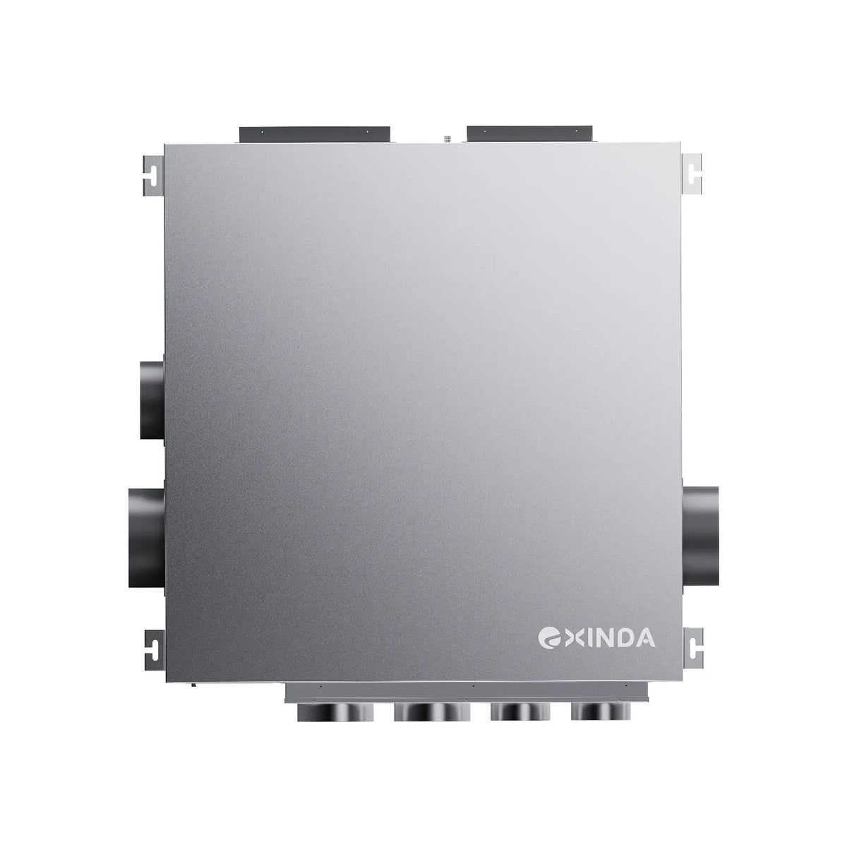
EXINDA Aura 3.5kW All-in-One Heat Pump ERV (HPERV)
A comfortable home. A considered use of space.
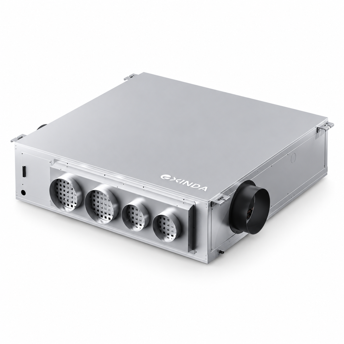
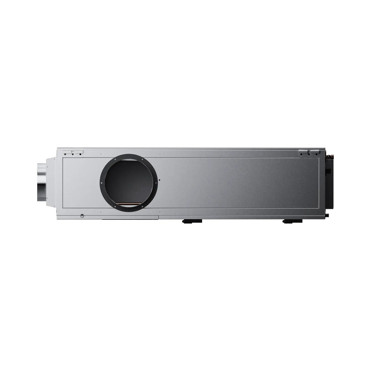
Bring heating, cooling and fresh air into compact flats and terraced homes with one discreet ceiling system. AURA 3.5 kW combines a slim 282 mm cabinet with built-in energy recovery, helping preserve usable space and a tidy exterior. Concealed ducts carry air to living rooms and bedrooms, while planned service access makes routine care practical.
Core Specifications
| Model | ICMPCGFF1AYE |
| System type | Ceiling-ducted all-in-one heat pump energy recovery ventilator |
| Rated heat-pump cooling / heating | 3.5 kW / 4.0 kW at the stated rating conditions |
| Balanced ERV ventilation airflow | 71–229 m³/h; 229 / 153 / 71 m³/h high / medium / low |
| Indoor supply airflow at 75 Pa | Approximately 730 m³/h cooling / 1150 m³/h heating at high speed |
| Outdoor heat-pump circuit airflow at 105 Pa | Approximately 1500 m³/h cooling / 1350 m³/h heating |
| Power supply | 208–240 V / 50–60 Hz / 1 Ph, hardwired |
| Maximum auxiliary heat / maximum input | 3 kW / 3900 W |
| MCA / MOP | 20 A / 30 A |
| Compressor | BLDC twin-rotary inverter |
| Refrigerant / charge | R32 (A2L) / 1.07 kg |
| Heat-pump operating range | −15 to 43°C outdoor |
| Auxiliary-heat operating range | −35 to 43°C outdoor |
| Sound pressure | 48 dB(A) at 1 m / 43 dB(A) at 3 m |
| Net dimensions (W × D × H) | 1168 × 1160 × 282 mm |
| Net / gross weight | 98 kg / 158 kg |
| Controller | Wall-mounted digital touch controller included; Wi-Fi and BACnet optional |
| Certification | CE CB SAA MEPS approved |
Sound values were measured with the unit ceiling-mounted, gypsum board below and piping connected, in high heating-airflow mode.
Heating and Cooling Performance
| Operating point | Heat-pump capacity | Input / efficiency | Rating condition |
|---|---|---|---|
| Cooling | 3.5 kW | 1465 W; EER 2.40 W/W | 35°C DB / 24°C WB outdoor; 27°C DB / 19°C WB indoor |
| Heating | 4.0 kW | 1687 W; COP 2.43 | 8°C DB / 6°C WB outdoor; 21°C DB / 16°C WB indoor |
| Low-temperature heating | 2.9 kW | 1650 W; COP 1.78 | −5°C DB / −11°C WB outdoor; 21°C DB / 16°C WB indoor |
| Minimum compressor condition | 1.7 kW | 1350 W; COP 1.30 | −15°C DB / −16°C WB outdoor; 21°C DB / 16°C WB indoor |
Below −15°C outdoor temperature, the compressor is disabled and the unit uses electric auxiliary heat only, up to 3 kW. Check the calculated heating load at the project design temperature before selection.
The submittal also reports ERV recovery contributions of 0.44 kW in cooling at 35°C and 0.73 kW in heating at 8°C. These are recovery contributions, not additional compressor capacity.
Ventilation and Airflow
Fresh-air ventilation, room air distribution and outdoor heat exchange use separate airflow ratings, shown below.
| Air system | Airflow / ESP | Evidence or design note |
|---|---|---|
| Balanced ERV ventilation | 229 / 153 / 71 m³/h | High / medium / low; ERV operating range −15 to 43°C DB |
| Indoor supply — cooling | Approximately 730 m³/h at 75 Pa | High-speed rated point; use the fan curve for other duties |
| Indoor supply — heating | Approximately 1150 m³/h at 75 Pa | High-speed rated point; use the fan curve for other duties |
| Outdoor circuit — cooling | Approximately 1500 m³/h at 105 Pa | Heat-pump heat-exchange circuit, not fresh-air delivery |
| Outdoor circuit — heating | 1350 m³/h at 105 Pa | Heat-pump heat-exchange circuit, not fresh-air delivery |
| ERV heating test at 0°C — low | 70 m³/h; 27 W | 77% SRE / 80% ASRE |
| ERV heating test at 0°C — high | 150 m³/h; 82 W | 73% SRE / 77% ASRE |
| ERV cooling test at 35°C | 70 m³/h; 26 W | 67% sensible total / 69% adjusted total efficiency |
MERV 13 indoor-air filters: 2, non-washable. MERV 4 return-air filters: 2, washable. MERV 4 condenser filter: 1, washable. The cross-flow heat exchanger is non-washable; the unit includes auto-balancing and exhaust defrost.
Installation and Controls
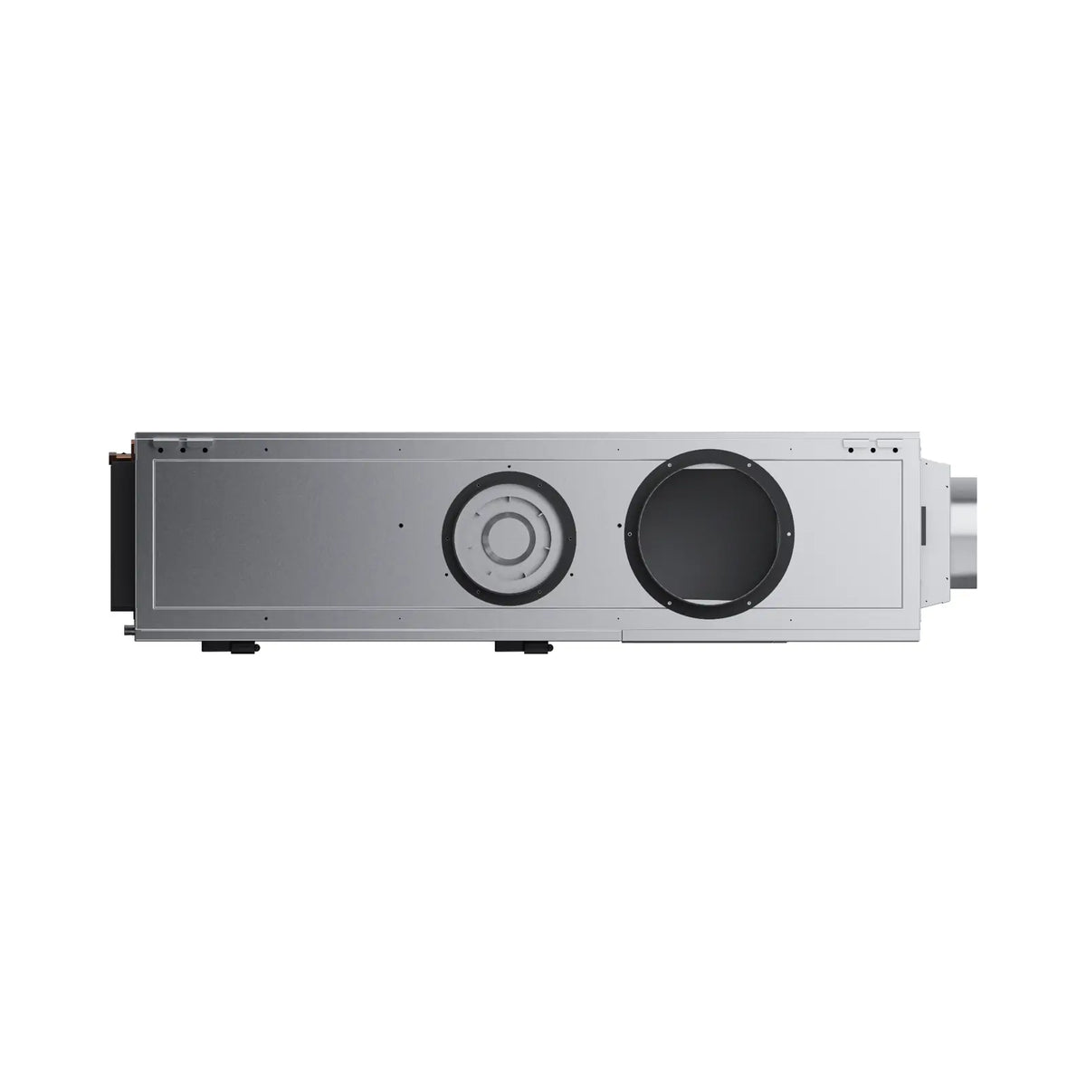
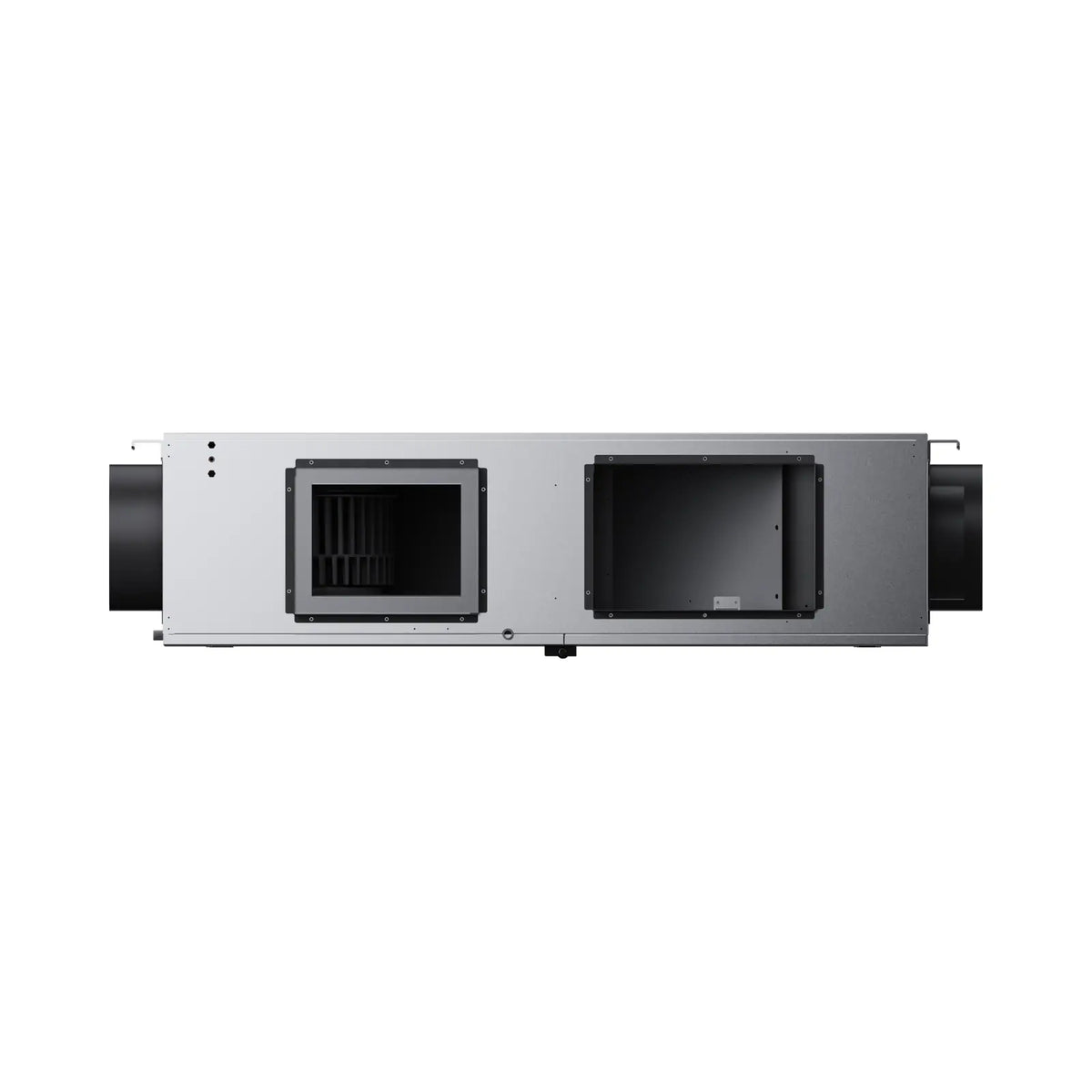
| Outdoor intake / exhaust | 305 × 203 mm / 254 × 203 mm rectangular |
| Minimum intake-to-exhaust separation | 1.25 m |
| Room return / bathroom exhaust | Ø203 mm / Ø152 mm round |
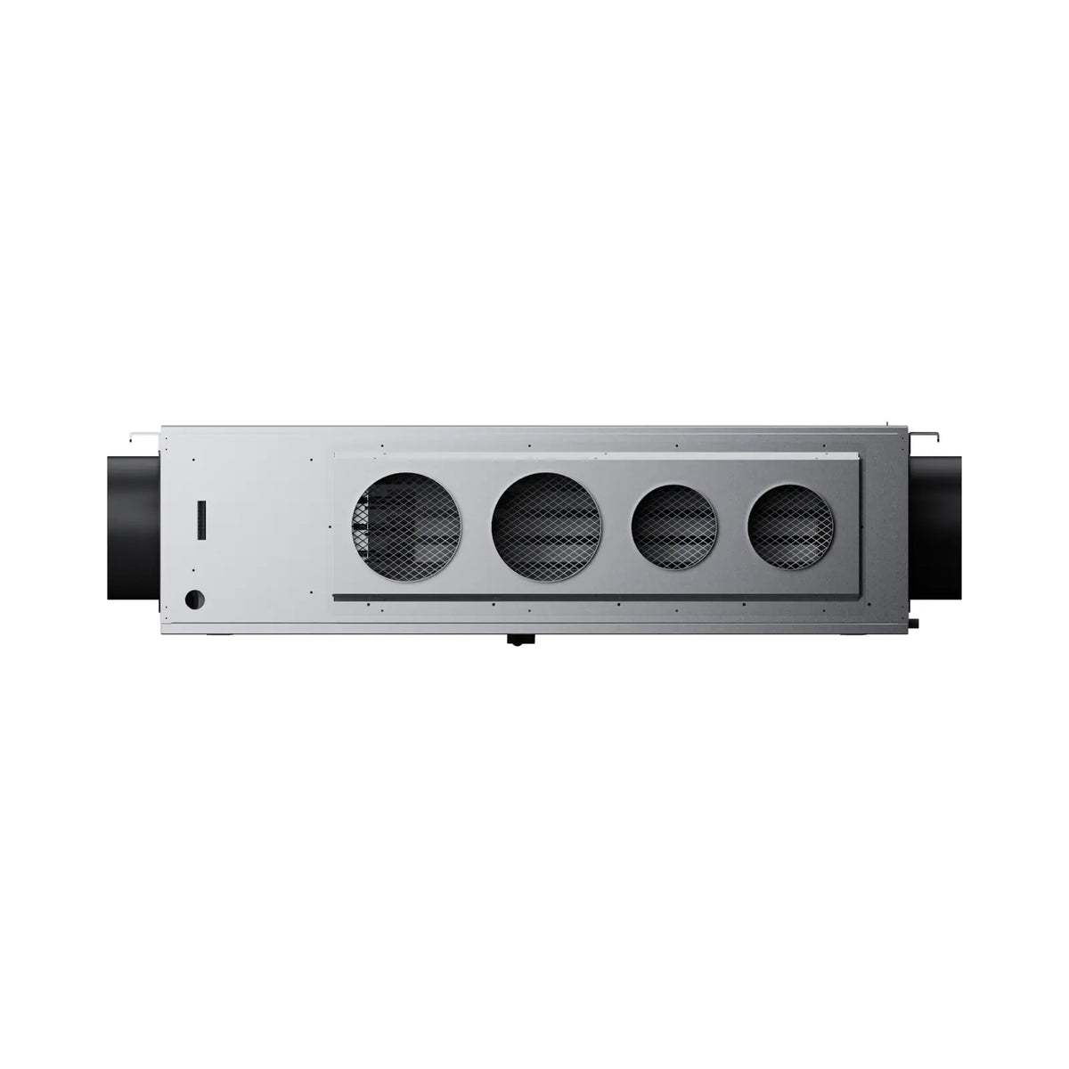
| Supply duct options | 711 × 203 mm rectangular or 4 × Ø152 mm round |
| Outdoor duct insulation | Minimum 20 mm with vapor barrier |
| Flexible outdoor connectors | Approximately 100 mm long and insulated for condensation control |
| Main service access corridor | 1516 mm minimum |
| Service opening depth | 575 mm minimum |
| Air-inlet service opening | 406 × 406 mm |
| Electrical compartment clearance | 406 mm minimum |
| Side clearance | 50 mm minimum |
| Controller cable | 5 m standard, 26 AWG; 55 m maximum |
| Condensate drains | Two NPS 1/4 in. (6.35 mm) drains; individual P-traps and minimum 1% slope required |
Confirm the final coordination drawing, ceiling structure, duct resistance, filter access, electrical access and condensate routing before construction.
AURA Technical Documents
Compare all AURA heat pump models
AURA Selection Questions
Can the system supply the sitting room and bedrooms?
Yes. A branched supply-duct layout carries air to the individual rooms, with a return route to the unit. Your designer allocates airflow to suit how each room is used.
Should I use the ceiling void or a floor-standing unit?
A ceiling unit is useful when retaining floor space matters. Allow room above the finished ceiling for the cabinet, ducts and servicing. Where the ceiling void is too shallow, consider a vertical unit in a suitable indoor service area.
Where can the unit go when planning a home or refurbishment?
A utility area can offer a useful position away from sleeping and sitting areas. Coordinate supports, vibration isolation, duct routes and an accessible service opening before the ceiling is finished.
How does the system connect through the external wall?
Separate air-intake and discharge ducts run to external openings or a coordinated louvre arrangement. This avoids a separate outdoor condenser. Include the openings, insulation and separation in the façade design.
How are fresh air and bathroom extract arranged?
The integrated ERV supplies fresh air and recovers energy from outgoing air. A bathroom extract route can form part of this arrangement, with the airflows and controls coordinated for the home.
How much ceiling space does the installation need?
The cabinet is 282 mm high. Allow additional space for supports, duct connections, drainage and the service opening when setting the finished ceiling level. Its concealed position preserves usable floor space in compact homes.
What access should the installer leave for servicing?
Position the access panel at the service side, with room to remove filters and reach electrical components and the condensate drain. Keep the opening clear of joinery, fixed finishes and other services.
Can drainage work where a gravity fall is difficult?
Optional external condensate-pump interlock provides an alternative arrangement. Plan the pump and pipe route together, keeping both accessible for cleaning and maintenance.
Can one development combine different sizes and layouts?
Yes. Compact flats, larger dwellings and guest accommodation can use different AURA sizes or installation formats. Send the project location, floor plans and unit mix for model selection and technical support.
Partner With EXINDA
Distributors & Dealers
Expand your HVAC offering with EXINDA heat pumps and ventilation systems, backed by product training and technical support.
Engineering Firms & Contractors
Get the performance data, submittals and engineering support you need to select equipment and move your project forward.
HVAC Brands
Bring your product ideas to market with EXINDA’s engineering, testing and manufacturing expertise.