
Modular heat pump water volume sizing starts with the water available to the operating modules—not simply the total water contained in the building. Establish the required active volume for each operating condition, then add buffer storage wherever the connected circuit falls short.
For engineers selecting EXINDA commercial air-to-water heat pumps, this means reviewing the equipment requirements, hydraulic layout and staging sequence together. A system with several modules can have very different storage needs when one module serves a small load, additional modules start, or part of the circuit is isolated.
The practical sizing sequence is:
- Establish the equipment manufacturer’s minimum active water volume.
- Check thermal storage against the intended runtime and temperature swing.
- Review defrost and modular operating conditions.
- Subtract the existing water volume that remains available in each condition.
- Select a buffer arrangement that covers the largest shortfall.
What does “active water volume” mean?
Active water volume is the water that remains hydraulically available and participates in temperature control during the operating condition being assessed.
This distinction matters in commercial buildings with zone valves, multiple pumps and isolated standby modules.
| System component | How to treat its water volume |
|---|---|
| Common headers and permanently connected pipework | Include where they remain part of the active circuit |
| Heat exchanger inside an operating module | Include according to the manufacturer’s definition of system volume |
| Fan coils or terminal branches with closing valves | Exclude when those branches can be isolated |
| Standby module with closed isolation valves | Exclude while isolated |
| Buffer tank | Include the effective volume participating in the operating cycle |
| Circuit beyond a separating heat exchanger | Assess separately; do not simply add its litres to the primary circuit |
A building may contain substantial water overall while leaving only a small circuit connected at low demand. Hydronic equipment guidance specifically identifies zone isolation and manufacturer-defined minimum volume as important sizing considerations. Buffer volume guidance
Water volume and water flow require separate checks
Water volume provides thermal storage. Water flow carries heating or cooling through the heat exchanger.
A system can meet the required flow rate and still contain insufficient storage for the intended control cycle. Increasing pump speed does not add water volume. Equally, a larger buffer tank does not guarantee adequate flow through every operating module.
Record both requirements in the design: active volume in litres or US gallons, and operating flow in L/s, m³/h or US GPM.
Modular heat pump water volume sizing: a worked example
Consider an illustrative heating plant with three modules connected to a common water circuit. During light demand, one module operates and the others remain off.
The following values are design assumptions, not EXINDA product specifications:
| Design input | Assumed value |
|---|---|
| Heat output during the operating stage being checked | 30 kW |
| Building heating load during that period | 10 kW |
| Desired minimum runtime | 5 minutes |
| Permitted storage temperature rise | 5°C |
| Existing effective circuit volume | 120 litres |
| Fluid | Plain water |
The heat output exceeding the building load is:
30 − 10 = 20 kW
Over five minutes, the water must absorb:
20 × 300 = 6,000 kJ
Using approximately 4.18 kJ/(kg·K) for water’s specific heat and 1 kg/L for density:
Required effective volume = 6,000 ÷ (4.18 × 5) ≈ 287 litres
The corresponding additional storage requirement is:
287 − 120 = 167 litres
For this operating condition, the buffer arrangement must therefore contribute at least 167 litres of effective storage.
A nominal 200-litre tank is a candidate only if its effective contribution covers that requirement and the other equipment, staging and defrost checks do not require more volume.
This calculation uses a thermal energy balance. The runtime-and-temperature-swing method is also described in this air-to-water heat pump design reference.
For what this looks like once it is built, a Montréal installation uses two thermal storage tanks to keep a single 12-ton unit running in long, stable periods on a radiant slab: The gas boiler stayed — it just stopped running above −25°C.
Which capacity should go into the calculation?
Use the output actually associated with the operating stage being assessed.
For an inverter module, that may be its lowest sustained output at the relevant water and outdoor temperatures. Startup or staging behaviour can produce a different output, so those conditions also need review.
Using the full installed plant capacity for every calculation can misrepresent low-load operation. Using only the lowest modulation value can miss a more demanding transition.
The temperature swing also needs careful definition: it is the permitted change in the storage water during the control cycle, not automatically the design difference between supply and return water.
For glycol mixtures, use the fluid supplier’s density and specific heat at the intended concentration and temperature.
How does module staging affect the result?
Review the operating conditions that change either the heat balance or the available water volume.
| Operating condition | Main sizing question |
|---|---|
| One module serving the smallest load | Can the available storage support the intended runtime? |
| Another module starting | Does the temporary output exceed what the load and storage can absorb? |
| Terminal zone valves closing | How much active water remains connected? |
| A module isolated for maintenance | Does the remaining plant still meet its volume requirement? |
| Defrost operation | Is sufficient accessible water and thermal energy available under the approved sequence? |
For each condition, determine the required effective volume and subtract the volume available in that same condition. Size the additional storage to cover the largest positive shortfall.
These operating requirements should not automatically be added together. The controlling requirement depends on which conditions can occur simultaneously.
Can one buffer tank serve several modules?
A shared buffer tank can serve a common circuit when the piping and control sequence make its storage available to the operating modules.
The review should establish how module pumps, isolation valves and temperature sensors interact with that tank. A shared tank’s nominal capacity alone does not demonstrate that the operating circuit can use all of it.
Where heating and chilled-water circuits are hydraulically separate, assess their volumes separately. Do not combine both circuits into one total to demonstrate sufficient storage.
What should be checked before selecting the tank?
Once the required effective volume is known, confirm:
- The tank’s usable water volume, pressure rating and temperature suitability.
- Connections and flow capacity appropriate to the proposed arrangement.
- Sensor positions that support the intended control sequence.
- Insulation and vapour sealing suitable for chilled-water service.
- Access for installation, inspection and maintenance.
Water-volume sizing should finish with a reviewable equipment selection and hydraulic arrangement—not only a litres-per-kW figure.
Frequently asked questions
Is there a standard litres-per-kW value for every modular heat pump?
No single ratio establishes the correct volume for every system. Apply the selected equipment’s requirements and check the operating stages, load, fluid and permitted temperature swing.
Does an inverter heat pump still need buffer storage?
It may. Modulation reduces output, but storage can still be needed when the smallest load is below sustained output, zones close, or the equipment requires a minimum accessible volume.
Does each module need its own tank?
Not necessarily. A common tank may serve a shared circuit. The hydraulic layout and operating sequence determine whether shared or individual storage is appropriate.
Can an expansion vessel replace a buffer tank?
No. An expansion vessel accommodates fluid expansion and pressure changes; it does not replace the active thermal storage required by the heat pump system.
Review your modular heat pump system with EXINDA
For an EXINDA commercial air-to-water heat pump project, send your proposed module selection, hydraulic schematic, estimated circuit volume, design water temperatures and glycol concentration to info@exindagroup.com.
EXINDA can work with your project team to review the equipment requirements and proposed water-system arrangement before installation.
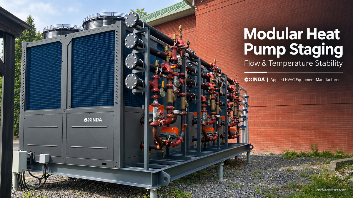
Cover: conceptual product composite, not an installation drawing.