
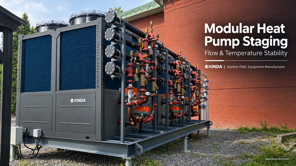
Modular heat pump staging must coordinate equipment capacity, water circulation and temperature control as modules start and stop. Stable operation depends on how the complete plant responds during these transitions, as well as on the steady-state performance of each unit.
EXINDA is an applied HVAC equipment manufacturer supporting North American commercial heat pump and chiller projects. For consultants, mechanical contractors and equipment partners, this guide identifies the hydraulic and control decisions to resolve before commissioning a multi-module plant.
Why can a plant become unstable when a module starts or stops?
Adding or removing a module changes available capacity. Depending on the piping and pumping arrangement, it can also change branch resistance, flow distribution and the temperature seen by the controller. If these changes occur faster than the control sequence can accommodate, the plant may repeatedly add and remove capacity.
For example, a branch valve opening in a shared-pump system can change flow through already operating modules. If an operating unit loses adequate flow and stops on protection, the controller may call for replacement capacity. Further starts and stops can prolong the disturbance. This is a possible failure sequence to investigate, not an inevitable result of shared pumping.
Successful staging therefore requires a coordinated response: establish the required flow, verify the unit is ready, enable capacity, and allow the system to respond before making another staging decision.
Review what changes during each transition
| Transition | What to verify | Useful trend data |
|---|---|---|
| Add a module | Branch circulation is established before compressor operation, without taking active units outside their flow limits | Branch flow, pump and valve status, flow proof, water temperatures |
| Remove a module | Capacity reduction and any pump post-run follow the approved sequence | Leaving-water temperature, run status, pump command and actual response |
| A module faults | Replacement capacity is staged according to the fault and restart logic | Alarm timestamps, available capacity, demand and restart attempts |
| Demand drops rapidly | Modulation, staging delays and active volume can accommodate the load change | Minimum output, active zones, control temperature and setpoint |
| A module enters defrost | For air-source equipment, the heating-loop response and permitted defrost overlap are covered | Defrost status, entering-water temperature and active module count |
Trend commanded and actual states separately where possible. A pump-enable command does not prove that adequate water is moving through the heat exchanger.
How do dedicated module pumps support staging?
A dedicated pump provides a defined circulation arrangement for its assigned module. Paired with suitable valves and a coordinated sequence, it can make branch operation easier to control and verify.
EXINDA can evaluate dedicated pumps and check valves for individual module branches. The review still needs design flow, required head, fluid properties, power supply and the proposed start/stop sequence. Shared headers continue to connect the branches hydraulically, so dedicated pumps should not be described as guaranteeing constant flow under every operating condition.
Check valves help manage reverse flow. They do not replace service isolation, and their pressure loss and opening characteristics belong in the hydraulic calculation. Shared-pump arrangements may also be suitable when pumps, valves and controls are designed and commissioned together.
For equipment scope, prefabricated headers and site connections, see modular heat pump pumping with dedicated pumps and check valves.
Why do buffer-tank location and sensor position matter?
A buffer tank contributes thermal mass only when its usable volume participates in the operating circuit. Its position also affects the water temperature reaching the heat pump and the temperature observed by the control sensor.
A return-side tank can be considered when the design objective includes moderating the temperature entering the equipment. A supply-side arrangement may serve a different control or distribution objective. Neither location should be treated as a universal requirement without reference to the selected equipment, hydraulic layout and control strategy.
Review the following together:
- Which water temperature controls module staging.
- Whether the sensor measures a representative mixed temperature or a local branch condition.
- Which water volume remains connected when zone or isolation valves close.
- How tank connections and pump operation engage the stored volume.
- How heating, cooling and any defrost operation affect the same sensor and circuit.
Tank volume alone cannot correct insufficient heat-exchanger flow or an unsuitable control sequence. Use the parallel commercial heat pump system water-volume guide for the separate active-volume calculation.
Define the staging sequence before selecting control settings
A useful control narrative describes what happens between a demand signal and stable equipment operation. It should cover normal starts, planned stops, fault recovery and minimum-load operation.
- Define demand: identify the controlling sensor, setpoint and permitted temperature band.
- Prepare circulation: identify the pump and valve actions required for the next module.
- Verify readiness: establish the applicable flow proof and equipment permissives.
- Enable capacity: follow the selected equipment's operating sequence.
- Observe the response: apply appropriate staging delays and minimum run/off times before another change.
- Handle exceptions: define fault lockout, restart permission, lead-lag rotation and available standby capacity.
Actual timings and thresholds must come from the equipment documentation and project controls review. Repeatedly resetting a fault or widening a temperature band should not substitute for identifying its cause.
Minimum stable output must also match the building's low-load periods. See four-pipe heat pump operating modes and turndown for the distinction between circuit, module and plant capacity.
Multi-unit control and BACnet integration
EXINDA supports a single BACnet gateway serving multiple 40-ton modular units. The gateway configuration, supported unit count and available control points should be confirmed for the selected equipment and project.
For a modular plant, define who controls staging: the equipment's group controller or the building management system (BMS). Agree which system issues plant enable and setpoint commands, and which manages individual module starts and stops. This avoids competing commands during a capacity change.
| Integration item | What the project team should confirm |
|---|---|
| BACnet interface | Whether the selected gateway supports BACnet/IP, BACnet MS/TP or both, and whether simultaneous operation is supported. |
| Gateway supply scope | Whether the gateway is included in the equipment quotation or supplied as an optional accessory. |
| Group control | The available master-follower configuration, maximum modules per group and responsibility for staging. |
| Network topology | Whether the gateway connects through the master controller or communicates with individually addressed modules. |
| BMS point access | Which plant commands and individual module status, temperature and alarm points are available, including read/write permissions. |
One gateway serving multiple units does not, by itself, establish that every follower unit can be read through the master. Use the approved communication topology and BACnet point list to define that scope.
During commissioning, check that commands reach the intended plant or module, that displayed states and alarms match local controls, and that communication-loss behavior follows the approved sequence. Gateway connectivity is one part of commissioning; hydraulic flow and equipment protections still require verification.
For integration planning, request the applicable gateway specification, single-unit or multi-unit wiring topology and BACnet point list from EXINDA. Provide the intended module count, BMS interface and required monitoring and control points so the configuration can be reviewed.
What should a multi-module commissioning check include?
Test transitions as well as steady operation. Where practical, begin with two modules to observe branch interactions, then verify the intended complete-plant combinations and operating limits.
- Record stable operation with the smallest intended active equipment combination.
- Add a module and observe flow and temperature on the units already running.
- Remove a module and check the remaining units and distribution system.
- Verify fault handling using the approved commissioning procedure; do not defeat protective devices.
- Review recovery after a permitted shutdown and any planned lead-lag change.
- For air-source heating, verify the applicable defrost sequence when conditions allow.
Use synchronized records of entering and leaving water temperatures, branch flow where measurable, pump/valve states, compressor status, setpoints and alarms. Agree the acceptance criteria before testing, including model flow limits, permitted temperature excursions and the expected recovery sequence. Record tests that remain outstanding because site conditions do not allow them.
EXINDA application support for modular plants
EXINDA's applied equipment approach connects product selection with hydraulic interfaces, controls and installation scope. Project discussions can include individual module pumping, prefabricated common headers for two-, three- or four-module arrangements, flanged site connections and Revit Kit availability for the requested configuration.
These resources help the project team coordinate equipment and site work. Dynamic plant performance must still be checked against the approved system design and commissioning results; available assemblies or models alone do not prove stability under every operating condition.
Frequently asked questions
Will one pump per module eliminate all staging problems?
No. Dedicated pumps can support branch circulation, but flow limits, shared headers, valve behavior, temperature sensing and the staging sequence still need coordinated design and verification.
Must the buffer tank always be on the return side?
No universal placement rule applies to every modular plant. Confirm the equipment requirement, active hydraulic path, control sensor and purpose of the tank before choosing its location.
Does a low minimum output guarantee stable operation?
No. Low-load capability is one part of the assessment. Active water volume, actual load, sensor response, pump/valve behavior and staging timing also affect operation.
What should be checked first after repeated module dropouts?
Review the first alarm and its timestamp alongside flow, water temperature and pump/valve changes. Identify the initiating event before adjusting the sequence or restarting equipment.
Request an EXINDA modular plant application review
Send your hydraulic schematic, module quantity and capacities, heating/cooling duties, design water temperatures and flows, pump/valve arrangement, tank and sensor positions, proposed control sequence, and any BMS interface and BACnet point requirements to info@exindagroup.com. For an operating plant, include relevant trend and alarm records.
EXINDA can review the product-side requirements with your team and identify the selection, integration and verification steps needed. Explore our commercial heat pump and chiller range for related applied HVAC equipment.